Introduction
The recent and ongoing development in the technology of rechargeable lithium batteries has been steadily increasing their performance and making them more safe, reliable, cheap, and easy to manufacture. All of this resulted in an increasing popularity of rechargeable lithium batteries, not only in portable consumer electronics, but also in traction, energy storage, maritime, industrial, military, and aerospace and other applications, where the high energy density, negligible memory effect, low self-discharge rate, and long life cycle of lithium batteries are highly desired characteristics. Despite the advantages, all rechargeable cells of lithium chemistry have a very strict allowed voltage range and certain charging temperature limitations. If operated outside these limits, they will fail prematurely and pose safety risks due to reactive components inside them. Also, because the mentioned applications usually require battery voltage to be significantly higher than that of a single cell, several cells have to be connected in series to attain the desired voltage.
This creates another problem: since lithium chemistry cells are very intolerant to overcharging, they do not have a natural equalization mechanism when connected in series (such as gassing in lead acid batteries), and any misbalance of charge between the cells will amplify with each cycle of operation if no countermeasures are taken, rapidly decreasing the usable capacity of the whole battery pack, and potentially causing its premature failure. In order to overcome these problems and to fully exploit the advantages of rechargeable lithium batteries, it is necessary to use an intelligent battery management system that can autonomously monitor the battery parameters at individual cell level in real time, and prevent them from going outside the safe operation limits. INNOLIA ENERGY has developed the BMS precisely for that purpose.
It is a highly flexible, state of the art digital battery management system with a unique set of features and utility functions that is designed to make the use of rechargeable lithium batteries straightforward and virtually maintenance-free, regardless of the battery size, capacity, voltage, and other factors. This document covers all aspects of using the Emus BMS, and aims to provide the user with an in-depth knowledge about its core functionality and utility functions, as well as with information about its proper installation and configuration together with connection diagrams, examples, and recommendations – all in order to help to utilize all of its capabilities and prevent most commonly faced issues.
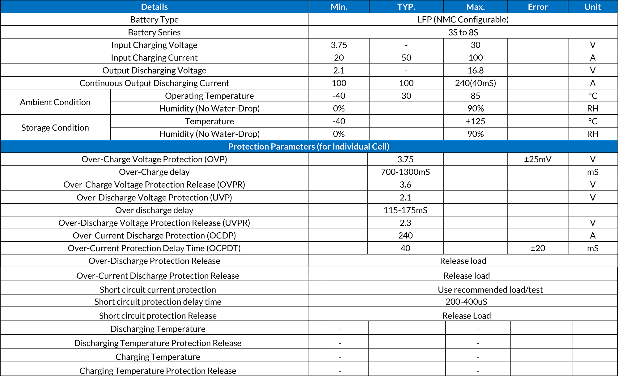
This document contains the specification for the INNOLIA 1S-8S (1-8 series) 3.75V- 30V 100A Hardware BMS (battery management system) board for the LFP lithium battery cells (NMC Configurable).
Electrical Characteristic (Ta = 25c) :

HARDWARE FEATURES :
(1) High-accuracy voltage detection circuit
- Overcharge detection voltage
- Overcharge release voltage
- Over-discharge detection voltage
- Over-discharge release voltage
- Discharge over current detection voltage
- Charge over current detection voltage
- Short-circuiting detection voltage
(2) Delay times are generated by an internal circuit.
(3) Low current consumption
- Operation mode 3.0μA typ., 6.0μA max. (VDD=3.2V)
- Ultra low power-down current at 0.1μA max.
(4) High-withstanding-voltage device is used for charger connection pins (CS pin and OC pin: Absolute maximum rating = 20 V)
(5) 0 V battery charge function “available” / “unavailable” are selectable
(6) Wide operation temperature range −40°C to +85°C
PASSIVE BALANCER :
The passive balancer is used to balance each and every cell of the battery pack. The extra charge in each cell is grounded, in this way each and every cell voltage will be balanced.
The main features of the balancer are :
(1) High-accuracy voltage detection circuit.
- Overcharge detection voltage
- Overcharge release voltage
- Standby detection voltage
- Standby release voltage
(2) Delay times are generated by an internal circuit
(3) Low current consumption (Standby Status).
- Operation mode Typical 2.5μA, Max 3.5μA (VDD=3.2V) l Ultra low power-down current at Max 0.5μA (VDD=2.0V)
(4) Wide operating temperature range −40°C to +85 °C