Introduction
The recent and ongoing development in the technology of rechargeable lithium batteries has been steadily increasing their performance and making them more safe, reliable, cheap, and easy to manufacture. All of this resulted in an increasing popularity of rechargeable lithium batteries, not only in portable consumer electronics, but also in traction, energy storage, maritime, industrial, military, and aerospace and other applications, where the high energy density, negligible memory effect, low self-discharge rate, and long life cycle of lithium batteries are highly desired characteristics. Despite the advantages, all rechargeable cells of lithium chemistry have a very strict allowed voltage range and certain charging temperature limitations. If operated outside these limits, they will fail prematurely and pose safety risks due to reactive components inside them. Also, because the mentioned applications usually require battery voltage to be significantly higher than that of a single cell, several cells have to be connected in series to attain the desired voltage. This creates another problem: since lithium chemistry cells are very intolerant to overcharging, they do not have a natural equalization mechanism when connected in series (such as gassing in lead acid batteries), and any misbalance of charge between the cells will amplify with each cycle of operation if no countermeasures are taken, rapidly decreasing the usable capacity of the whole battery pack, and potentially causing its premature failure. In order to overcome these problems and to fully exploit the advantages of rechargeable lithium batteries, it is necessary to use an intelligent battery management system that can autonomously monitor the battery parameters at individual cell level in real time, and prevent them from going outside the safe operation limits. INNOLIA ENERGY has developed the BMS precisely for that purpose. It is a highly flexible, state of the art digital battery management system with a unique set of features and utility functions that is designed to make the use of rechargeable lithium batteries straightforward and virtually maintenance-free, regardless of the battery size, capacity, voltage, and other factors. This document covers all aspects of using the Emus BMS, and aims to provide the user with an in-depth knowledge about its core functionality and utility functions, as well as with information about its proper installation and configuration together with connection diagrams, examples, and recommendations – all in order to help to utilize all of its capabilities and prevent most commonly faced issues.
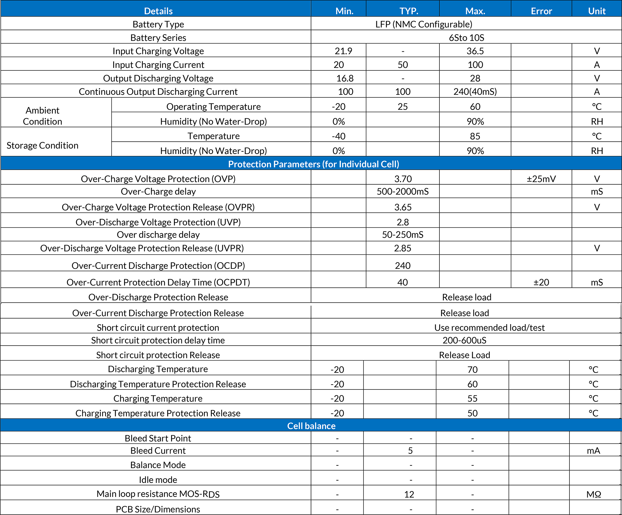
This document contains the specification for the INNOLIA 6S-10S (6-10 series) 21.9V- 36.5V 100A software Communication BMS (battery management system) board for the LFP lithium battery cells.
This BMS has multiple extra ordinary features such as WIFI, Bluetooth, CAN, RS-485 and RS-232 for BMS communications.
Electrical Characteristic (Ta = 25c)

Functional Overview
Cell Monitoring
Individual cell monitoring is a fundamental and one of the most important functions of BMS. It is a complex, multi-part process in which certain roles are distributed between Cell Modules and the Control Unit. Each Cell Module, once mounted on a cell, starts its work routine during which it measures the cell’s voltage and its own temperature (as well as the external temperature, if applicable), and uses the measured values to regulate the balancing current in an attempt to keep the cell’s voltage lower than the balancing threshold, while at the same time keeping its own temperature lower than a certain maximum value to protect itself from overheating.
Current measurement
The measurement of the battery current in BMS comprises continuous, executed processes. The Control Unit continuously measures the analog signals given by BMS Current Sensor using a high sample rate analog-to-digital converter peripheral, and periodically stores averaged measurement results for further processing. The averaging is needed in order to mitigate the effects of thermal, quantization and other noises.
SOC estimation
State of Charge estimation in BMS is mainly based on the coulomb counting technique, with few exceptions where the SOC value is adjusted by cell voltage in order to mitigate its drawbacks. The coulomb counting is done in sync with the current update process: every newly determined momentary current value is multiplied by the update period, and the result, regardless of its sign, is accumulated into volatile memory as Battery Charge value (in Ah). This value is later compared to “Capacity” configuration parameter value in order to determine the SoC expressed in percentage.
Cell Balancing
“Balancing” stage is entered when the maximum cell voltage is more than or equal to the “Fully Charged Voltage” parameter value. At this point, the difference in stored energy between the cells is proportional to the difference in their voltages, therefore during this stage BMS takes several actions to eliminate that difference and balance them. Firstly, the balancing threshold is by default equal to” Fully Charged Voltage” parameter value as well, therefore the corresponding Cell Module(s) naturally start to divert the charging current through their shunt resistors in attempt to prevent the cell voltages from rising further. Secondly, the charging current is also controlled respect in to similar criteria; however, this process differs depending on what type of charging device is used.
Battery Protection :
Battery protections during discharge, BMS protects the battery from operation beyond certain limits of its parameters (voltage, temperature, current) by deactivating the general-purpose output pin function. This pin function is intended for disconnection of battery from the load.
Hardware Protection Features :
- Cell Under-Voltage protection prevents the battery from being discharged further if the voltage of at least one of the cells is below the threshold set by the corresponding “Activate at” parameter;
- Cell Over-Voltage protection prevent the cells from being overcharged during regenerative processes, and is activated if the voltage of at least one of the cells is above the threshold set by the corresponding “Activate at” parameter;
- Discharge Over-Current protection is activated if the measured discharge current is above the threshold set by the corresponding” Activate at” parameter, thus preventing the battery from being discharged at a rate that is higher than specified by the cell manufacturer;
- Charge Over-Current protection disconnects the main contactor if the measured charge current is above the threshold set by the corresponding” Activate at” parameter, thus preventing the high currents during regenerative processes from potentially damaging the cells;
- Cell Module Over-Heat protection prevents the battery from being operated when the temperature measured by the internal cell module’s temperature sensor is above the threshold set by corresponding” Activate at” parameter, which is likely to be caused by sparking/bad contact, an equipment failure, or a bad cell;
Battery Parameter Monitoring :
Display unit is provided to monitor battery parameters stated below,
- Pack Voltage
- Charging/Discharging Current
- SOC/SOH
- Battery Pack details
- BMS protection Parameters
- Individual string voltages
- Temperature of pilot cells
Communication Features :
RS485
- 12MBPS Data rate
- Low powertrans receiver
- Half duplex configuration
- All transmitter Outputs and receiver Inputs are Protected to±15KV
- Low Current 1µA in sleep mode.
- Current limiting and thermal shutdown for driver overload protection
RS232
- standards from a 3.0V to 5.5V power supply
- 120kbps data rate.
- Enhanced ESDspecifications :
- ±15kV Human Body Model
- ±15kV IEC61000-4-2 Air Discharge
- ±8kV IEC61000-4-2 Contact Discharge
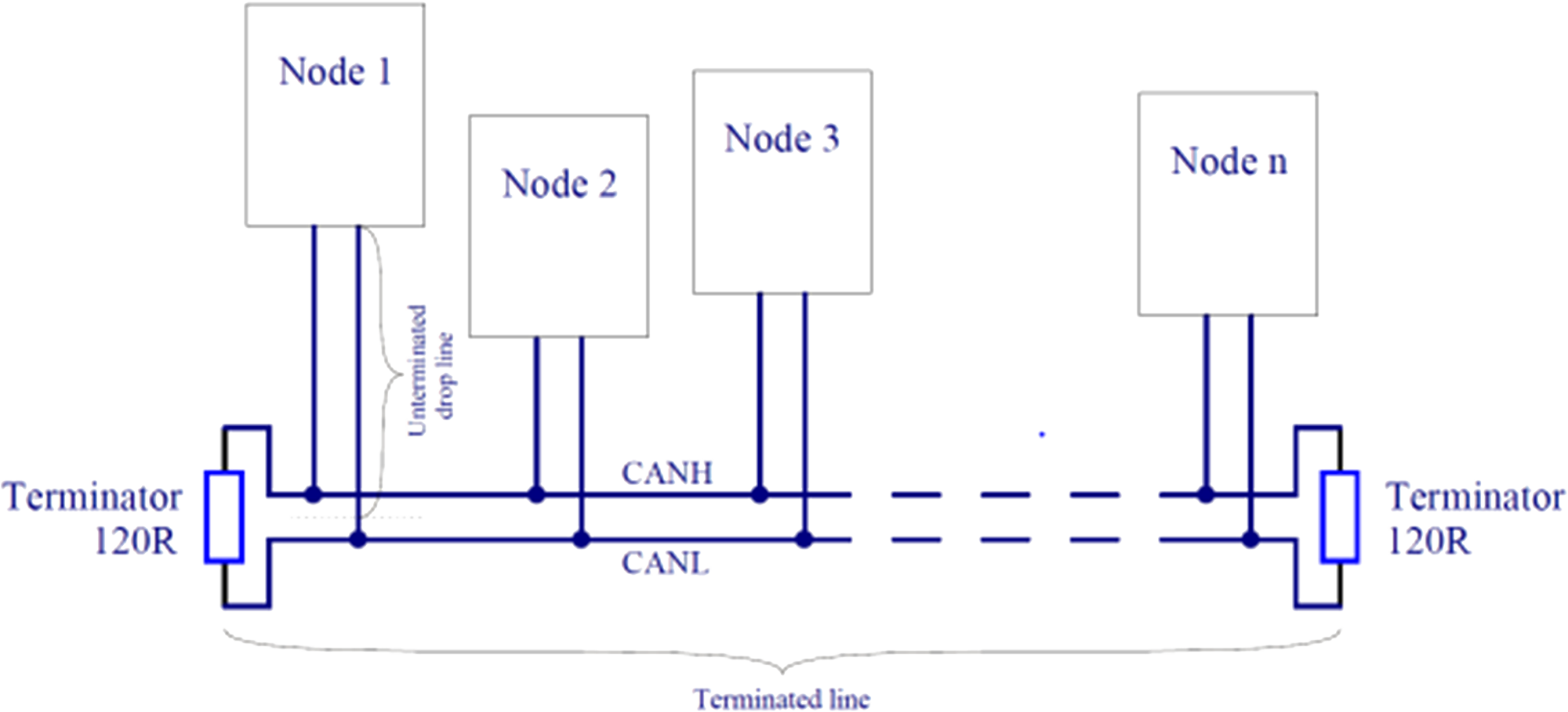
CAN Bus :
-
- 1MBPS Data rate
- Very low standby current 5µA.
- Protection Against Damage Due to Short-Circuit Conditions (Positive or Negative Battery Voltage).
- Automatic thermal shutdown protections.
- High-Noise Immunity Due to Differential Bus Implementation.
- Temperature ranges :
- Extended (E): -40°C to+125°C.
- High (H): -40°C to+150°C
- Communicate with other CAN-equipped Emus BMS components;
- Control certain third-party charging devices;
- Transmit BMS activity data (either periodically or by request);
- Receive new configuration parameter values and other special messages

Wi-Fi
- Wi-Fi protocols – 802.11b/g/n
- Frequency range – 2.4 GHz ~ 2.5 GHz (2400 MHz ~ 2483.5MHz)
Hardware
- Peripheral interface – UART/HSPI/I2C/I2S/IR Remote-control
- Operating temperature range –40 °C ~ 85°C
Software
- Wi-Fi mode Station/SoftAP/SoftAP +Station
- SecurityWPA/WPA2
- Network protocols IPv4, TCP/UDP/HTTP/FTP
Bluetooth
Hardware features
- Typical -80dBmsensitivity
- Up to +4dBm RF transmit power
- Low Power 1.8V Operation ,1.8 to 3.6VI/O
- UART interface with programmable baud rate
Software features
- Supported baud rate:9600,19200,38400,57600,115200,230400,460800.
- Auto-connect to the last device on power as default.
- Auto-reconnect in 30 min when disconnected as a result of beyond the range of connection